Last night I rewired the grounding situation for the reverb send and receive RCA jacks. Originally I had the ground tied to chassis at that point, like older Fenders I had seen. This apparently had the effect of inducing hum into the reverb amp section, so that every time I turned up the reverb knob, it'd hum like crazy.
I isolated the RCA jacks from chassis ground at that point, using teflon washers on both sides of the jacks, and made sure the "grounding" tab of the jack was on the insulated side, not touching chassis. I then ran a separate ground wire to my ground bus, where all grounds meet up.
Soldered in, cleaned up, plugged in...
Perfectly quiet thick reverb!
Next step : design a MOSFET high voltage stage for the insertion of my solid state section.
Wednesday, March 21, 2012
Monday, March 19, 2012
Amp Testing
So, I threw in the amp, and speakers, wired up the reverb cables with some teflon insulated fancy cable and turned it on. The dust from sitting in the garage smoked off, but it sounded great! Just got to tweak the reverb some and install the other (solid state) channel.


Sunday, March 18, 2012
Cabinet Build
FINALLY - got around to making a cabinet for this guy...


Half-blind dovetails, pine cabinet, routed over corners and cutout for control panel, English Chestnet stain, hand-rubbed spar varnish.
Now to let it cure and drop in the electronics!
Saturday, December 11, 2010
Circuit Edits
So, while turning the amp on for the first time, I found it squealing and way noisier than could be used in any kind of setting. I ran through my notes and discovered I had wired the primary of the output transformer out of phase, that is the secondary was feeding the feedback loop out of phase, so that it wasn't taming the amp - it was making it feedback on itself. Hence the squeal and super loud noise. I remedied this by swapping the transformer primary leads on the tube sockets. Problem solved.
Another fix - the control grid of the 7591 tubes was much lower than I would have liked - sitting at around 305V, rather that 370V-375V that it should be. The extra PI filter that I had running of one of the HT leads was knocking down the voltage a bit too much. I stuck a pot across the existing resistors and varied it until I had approximately 365V-370V at that point. There was a sequence of adjustments, because as I changed that value, the plate voltage changed, and so did the bias. All 3 were reacting with each other. I eventually reached a happy medium. I connected a 22k-ohm and 33k-ohm resistor in parallel with each other.
Feedback - The Fender circuit has an 820-ohm resistor feeding back into the phase inverter stage (pre-7591), while the Fisher has a 2200-ohm in parallel with a 1000pF cap. Again, a happy medium. I have a decade resistor box that I ran across the feedback point and listened to the circuit with different feedback resistors. 1k-ohm sounded good. I replaced the jumper with a 1k-ohm resistor in parallel with an 1800pF cap.
Reverb make-up gain - tube replacement. While testing out the amp, I found that a 12AX7 (at least any of the ones I had) were far to noisy to be used in the make-up gain section for the reverb return. I threw in a used 12AU7 in there and that cured my problem, without making the amp sound noticeably different. I may consider a JFET return amp, instead of the 1/2 of a 12AX7, leaving the other half for the mixer circuit. I might be able to use the unused (when modified) section for gain for the solid state preamp I intend to use as a channel option to the tube preamp.
Wednesday, December 8, 2010
Project End
I finally put the amp completely together, and this project is at an end. Through many mistakes, mostly with wiring, I managed to build a working amplifier.


The bias board that I had originally built on perfboard was rebuilt. I was not happy with the quality of the work on this board. I decided to cut up some panelboard and mount some eyelets to the board, using a layout that I quickly drew up on graph paper, as a guide. The result is a more uniform look, as well as studier construction. I don't have to worry about the hot glue coming off, or perfboard becoming brittle and breaking off while in use.


I also added another PI filter after the choke in the power supply, for the 7591 grids (pins 4/8). With the bias voltage sitting around 23V, I was able to monitor the voltage while adjusting a potentiometer for that voltage. I mounted the extra sub circuit on terminal strips, mounted to the main fiberglass board.


Tomorrow (and beyond the time frame of my electronics class) I intend to make further investigations into the workings of this amp. I am overall satisfied with the outcome of my hard work. This is a far cry from the quality of my first tube amp project. As with anything, good practice makes for better results.
The last few days were probably the most intense. Building the amp (actually putting the pieces into place) is very time consuming. More so than anyone would first assume. There are commercial kits one can buy, costing anywhere from $800-$1500. I'd say, based on the time it takes to get everything together, that price is actually quite fair. I am happy that I laid this amp out from my own layouts, however. It gave me the advantage to use parts that I had and to make arrangements for custom circuitry.
Sat 12/4 (6HRS)
Sun 12/5 (4 HRS)
Mon 12/6 8:30-12:30 & 8:30PM-12AM (7.5 HRS)
Tues 8PM-12:30AM (4.5 HRS)
Friday, December 3, 2010
Putting things together
Worked on (the start of) finalizing this amp:
- Mounted transformers properly
- Mounted/installed capacitor board
- Installed RCA jacks for reverb
- Installed 1/4" speaker output jack
- installed power switch (not tight)
- Installed all front panel controls (potentiometers, switch)
- Installed 4 1/4" input jacks
- Installed/connected/soldered front panel controls ground wire
- Installed front panel wiring (shielded multi-pair or single, where appropriate)
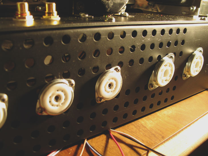
- Installed all tube sockets
- Installed ground point at power transformer mounting screw
- Mounted front panel to chassis
- Connected choke wires to capacitor board
- Drilled extra hole in chassis for terminal strip for rectifier circuit


Thursday, December 2, 2010
Solid State Power Supply
Quick bread boarding this morning - 9V power supply for solid state preamp stage. I considered a chip-regulated power supply, however, the simplicity of a zener diode resolved that choice. Here is the schematic:

I am using an integrated bridge rectifier, not individual diodes, but I don't have a simulation symbol for a bridge in LTSPice (that I know of).
7:30-8:30AM (1HR)
Subscribe to:
Comments (Atom)